[Total No. of Questions - 8]
[Total No. of Printed Pages - 2]
B.E. VIIIth Semester Examination
BE-VIII/6(A)
211420
Electrical Engineering
Course No. EE - 802
Power System-III
New Syllabus
Note: Attempt any five questions, all questions carry equal marks.
-
- How do you form bus admittance matrix [YBUS], by inspection? Explain.
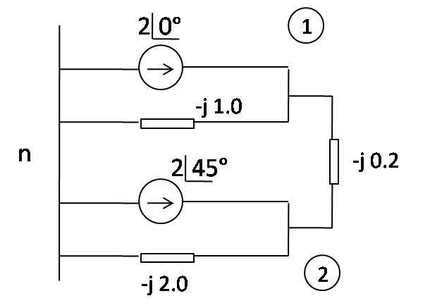
- An admittance diagram for a two bus network is as shown. Find [YBUS]. Also draw impedance diagram and by inverting [YBUS], obtain v1 + v2.
-
- A 3 Bus n/w is as shown. The series impedance and shunt admittance of each line are 0.026 + j0.11 p.u and j0.04 p.u respectively. The specifications are shown in table:


For bus 2 the minimum and max reactive power limits are 0 and 0.8 p.u:- Form [YBUS]
- Find P2o, Q2o, P3o, Q3o
- Find [Jo]
- Give the flowchart for load studies using Newton-Raphson method. How does the method get modified to account for PV buses?
- A 3 Bus n/w is as shown. The series impedance and shunt admittance of each line are 0.026 + j0.11 p.u and j0.04 p.u respectively. The specifications are shown in table:
- Explain in detail methods of improving power system stability.
-
- List the factors determing the stability limit.
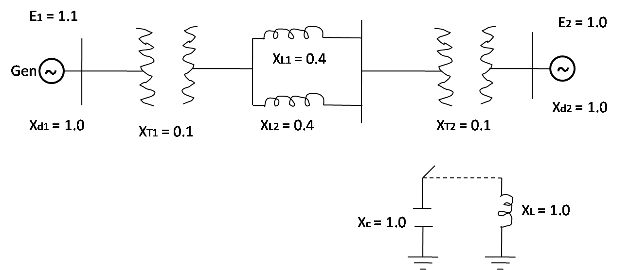
- Find the max. steady state power when:
- Static capacitor is connected
- Replaced by inductive reactor of same reactance. What will be the value of P and Q in both cases if del = 30o.
-
- Give mathematical derivation of swing equation.
- An alternator with X'd = 0.1 p.u. is delivering power of 0.8 p.u. at a termial voltage of 1.05 p.u. The inertia constant is 4 MJ/MVA. This alternator is suddenly synchronised to an infinite bus through a transformer of reactance of 0.1 p.u. and a double circuit transmission line of 0.4 p.u. reactance each. Assuming the infinite bus voltage to be 1.0 p.u, determine swing equation.
-
- Describe different types of reactive power compensators.
- Establish the relationship between the incremental changes of Q, P and V in a load node.
-
- Define surge impedance with reference to transmission line and deduce from 1st principles and expression for it.
- A generator with a generated voltage ER is connected across the lossless transmission line of length x metres, the load across this line is 1/4th of the surge impedance of the line. The generator surge impedance is 1/2 of the surge impedance of line. Draw the Bewley's Lattice diagram.
- Write short notes on:
- Limitations of Newton's Raphson method.
- Decoupled load flow analysis.
- Application of the swing curve.
- Bewley's lattice